FEM & CFD simulation
Simulate instead of trial and error: strength, deformation, natural frequencies, flow and heat are verified on the 3D model – before anything is manufactured.
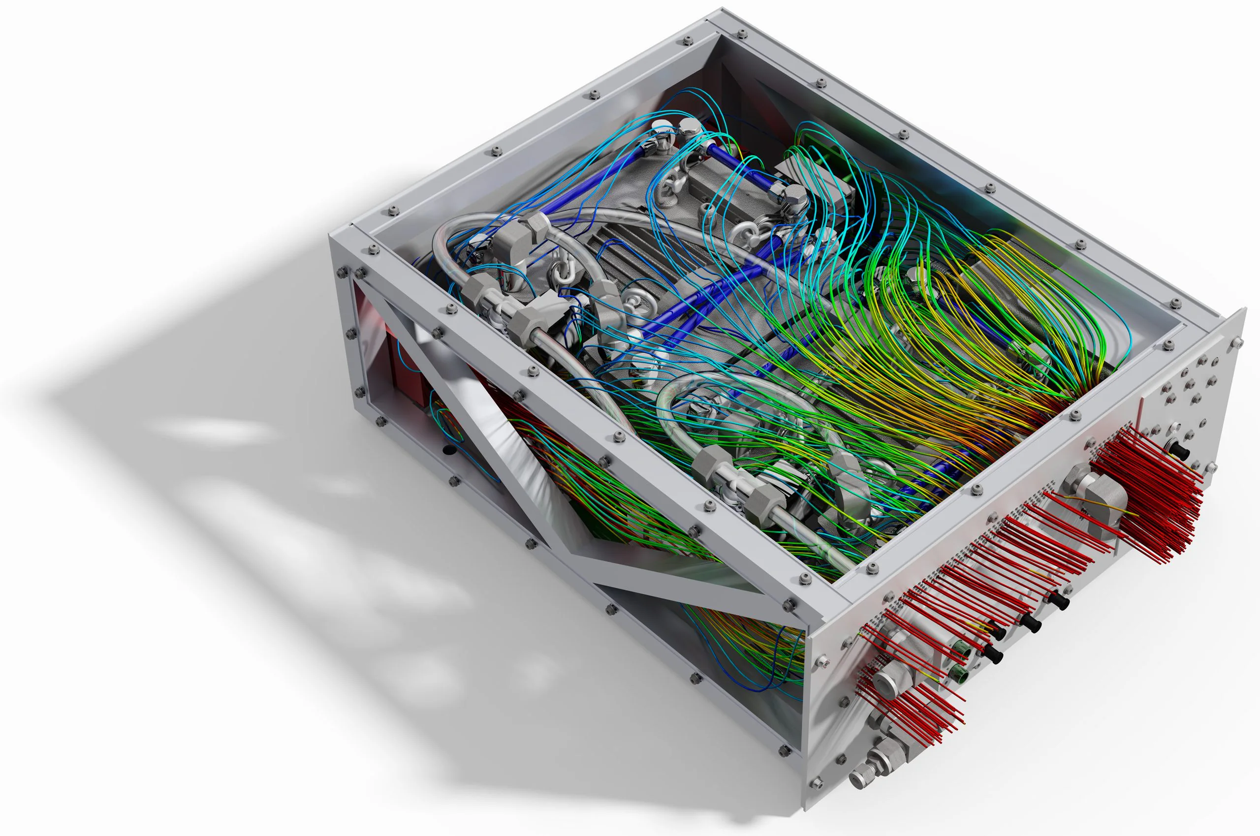
Simulations replace costly manufacturing iterations. Forces and moments are applied as they act in operation – derived from the design, not estimated. The result is a release for manufacturing that is based on numbers: stresses, deformations, safety factors, temperatures.
Because design and simulation come from a single source, the results flow straight back into the model: material where it is needed, saved where it is not. Geometry adjustments shift natural frequencies out of the critical range, and flow paths are improved before a prototype is built.
fem · angle bracketequivalent stress
cfd · wind tunnelcomputed live
Drag the body with the mouse – or click it and use the arrow keys.Drag the body with your finger.
dragFD mN/m
cD = – · mean – mN/m · last 10 sliftFL mN/m
cL = – · mean – mN/m · last 10 scylinder Ø 0.1 mm · forces per metre of span · Re = 68 · 2D
Scope of services
Structural analysis (FEM)
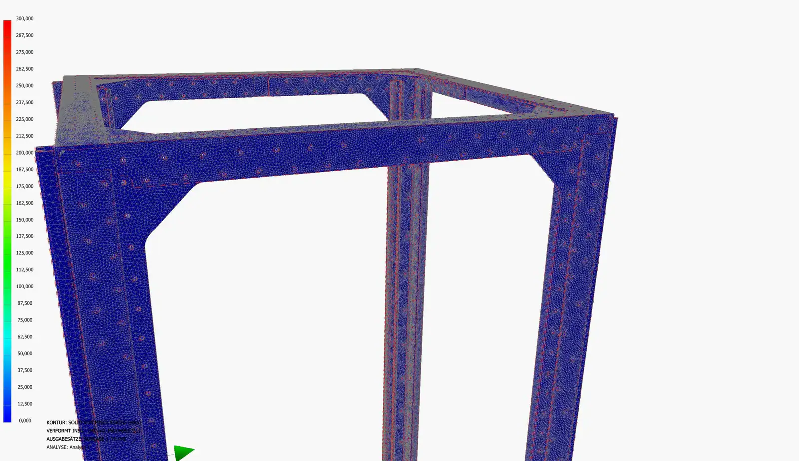
Stresses, deformations and safety factors of highly loaded structures. Components are dimensioned precisely and operational strength is verified before manufacturing.
Natural frequencies & vibration
Modal analysis of components and assemblies. Frequency ranges are shifted by adapting the geometry so that nothing vibrates or fatigues in service.
Flow simulation (CFD)
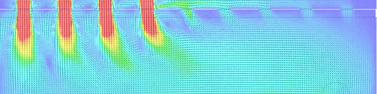
Air and fluid flows in housings, devices and plants: vortices, dead zones and bottlenecks become visible – and the flow path is improved before a prototype is built.
Heat & cooling
Combined simulation of heat and air flows shows which temperatures occur in operation – and whether the cooling is sufficient.
Dynamics & crash
Time-dependent processes, impact and crash with LS-Dyna – when static analysis is not enough.
Calculation & dimensioning
Analytical dimensioning and verification with MathCAD – traceably documented, as a supplement or cross-check to the simulation.
How we work
- Question & loadsWhat should the simulation answer? Load cases and boundary conditions are derived from the design.
- Model & meshThe 3D model is prepared for calculation: sensibly simplified, meshed, assigned materials and boundary conditions.
- CalculationFEM with Nastran, CFD with Ansys Fluent, dynamics and crash with LS-Dyna.
- EvaluationStresses, deformations, temperatures, flow images – assessed against your requirements and safety factors.
- Back into the designChanges are implemented directly in the model and recalculated if necessary – until release.
Tools
The right program for every task – the models come straight from the design.
- Nastran FEM
- Ansys Fluent CFD
- LS-Dyna dynamics & crash
- MathCAD calculation
- Inventor 3D models
What you get
- Report with load assumptions, boundary conditions, results and assessment
- Stress, deformation and temperature plots – as animations on request
- Safety factors and a clear release recommendation
- Design change proposals – implemented directly in the model on request
Examples from our projects
Frequently asked questions
Do we need a 3D model?
Not necessarily. If you have a model, we use it – as a native file or as STEP. Otherwise we build it from your drawings or sketches.
What is the difference between FEM and CFD?
FEM (finite element method) calculates the structure: stresses, deformations, natural frequencies. CFD (computational fluid dynamics) calculates the flow of air or liquids and heat transfer. The two often go together – for example when a housing has to be cooled and stiff at the same time.
Can we commission the simulation alone?
Yes. Simulation is available as a stand-alone service for your design – or as part of a design carried out by us.
Other areas of expertise
- CAD design
- Plant planning
- Prototype development
- Technical documentation & CE
- Data management & BOMs
- Assembly instructions
- Development & automation
- Future-oriented design
- External design department
From Pforzheim for clients throughout Germany – with on-site meetings as well as installation and assembly support. More about the region