Future-oriented design
Staying competitive means designing today so that tomorrow fewer parts, fewer process steps and less material are needed – while variants, service and new regulations still have room.
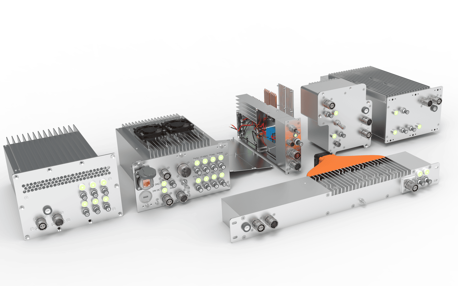
Design determines most of the later manufacturing costs – while causing only a small part of them itself. Saving parts here, choosing suitable manufacturing processes and planning variants from the start saves money on every part produced.
For us, future-oriented means: as simple as possible, as robust as necessary, designed for manufacturing and assembly, repairable and open to variants. We check existing designs for savings potential, replace welded and milled parts with bent sheet metal parts, design lighter, standardise standard parts, build modular systems and configurators, consider costs over the entire service life, modernise existing machines and implement the new Machinery Regulation, which applies from 20 January 2027.
Staying competitive
Price, delivery time and quality decide who gets the order – and all three start in design.
Fewer parts
Every part that is dropped saves drawing, manufacturing, storage, assembly and inspection.
Shorter delivery times
Laser cutting and press braking instead of sawing, milling and welding – bent parts are quick to make, even in small quantities.
Consistent quality
Bent parts are made without welding distortion – which saves straightening and rework.
Variants without redesign
Modular systems and configurators create new sizes from proven building blocks.
Service & spare parts
Bolted assemblies can be replaced, repaired and retrofitted.
Regulations in view
Machinery Regulation, standards and documentation are considered from the start.
Minimum and maximum principle
Both principles come from business economics and fit design perfectly: either a required function is achieved with as little effort as possible – or the best possible result is achieved with a fixed amount of material, space and budget.
Minimum principle
The goal is fixed, the effort is kept as small as possible: the same function with less material, fewer parts and fewer process steps – for example one bent part instead of a welded assembly.
Maximum principle
The effort is fixed, the result is made as large as possible: more parts from the same sheet, more function in the same space, more stiffness from the same sheet thickness – for example with beads and flanges.
Example from the animation: mass of the bracket
Mass m = ρ · V, for sheet metal parts V = A · s (steel: ρ = 7.85 g/cm³)
Weldment of 6 parts: V = 262.75 cm³ → m = 7.85 g/cm³ · 262.75 cm³ = 2.06 kg
Bent part, s = 3 mm: A = 350.80 cm² → V = 350.80 cm² · 0.3 cm = 105.24 cm³
→ m = 7.85 g/cm³ · 105.24 cm³ = 0.83 kg
Saving = 1 − 0.826 kg / 2.063 kg = 60 %
Example values. The actual design depends on load, stiffness, quantity and manufacturing.
Bent sheet metal parts – from blank to machine
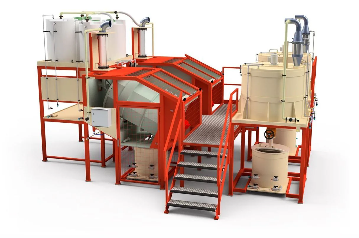
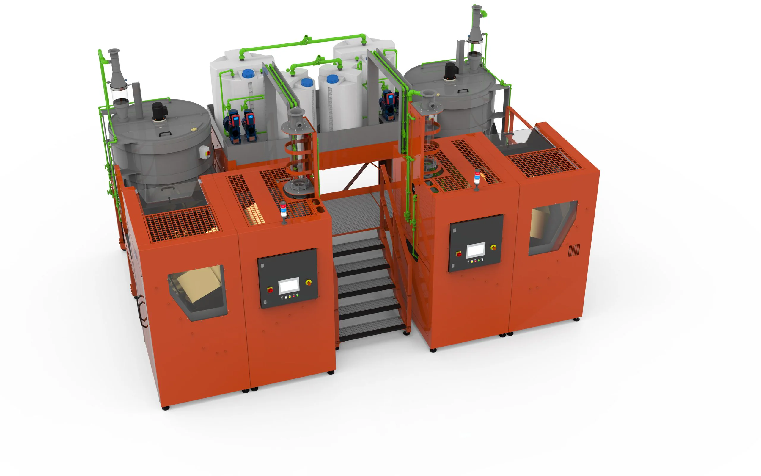
Many components can be designed as bent sheet metal parts: brackets, consoles, housings, panels, doors, control cabinets and entire frames made of bent profiles. The animation shows the way from the welded bracket to the bent part – and how many bent parts become a special-purpose machine. One example from our projects is the plant for precious metal recovery: formerly with a welded frame, today with a sheet metal frame.
- BeforeBracket made of six milled and welded parts.
- AfterOne bent part with tabs, reliefs and beads.
- BlankFlat pattern to DIN 6935, laser-cut.
- BendingFive bends, the back gauge moves along.
- MachineFrame, panels, doors and control cabinet made of bent parts.
- ResultParts, welds, mass – and further potential in the housing.
What matters with bent parts
- Radius & thicknessThe same inner radius throughout the part saves tool changes; the radius depends on material and sheet thickness.
- Bend reliefsWhere a flange ends at an edge, a relief prevents cracks and bulging.
- Flange lengthDuring bending the flange must rest safely on both die shoulders – the minimum length depends on the V opening.
- HolesHoles close to the bend line distort – so keep them at a distance or make them after bending.
- Bending sequenceEvery bend must be reachable with punch and die without already bent flanges colliding.
- Stiffness through shapeBeads, flanges and return flanges stiffen the sheet – often instead of ribs and reinforcements.
Developed length to DIN 6935
L = a + b − v (a, b: outer dimensions of the legs up to the intersection of the outer surfaces)
v = 2 · (r + s) − π · (180° − β)/180° · (r + k · s/2) for 0° ≤ β ≤ 90°
k = 0.65 + 0.5 · lg(r/s) for r/s < 5
Example s = 3 mm, r = 3 mm, β = 90°: k = 0.65 → v = 2 · 6 − π/2 · 3.975 = 12 − 6.24 = 5.76 mm
Bracket with 4 bends in one direction: L = 26 + 92 + 112 + 31 − 3 · 5.76 = 243.7 mm
β is the opening angle after bending. For 90° < β ≤ 165°: v = 2 · (r + s) · tan((180° − β)/2) − π · (180° − β)/180° · (r + k · s/2).
Further potential: the machine housing in the animation can be built even more simply. Self-supporting panels with flanges replace corner posts and top frame, the handles are bent directly into the doors and the side parts of the operator panel into its shell – 33 bent parts become 33 − 4 − 4 − 2 − 2 = 21.
Lightweight design with simulation
Instead of oversizing across the board, we calculate where a part is actually loaded – and use material only where it carries load.
FEM instead of margins
Stresses and deformations are calculated, not estimated – wall thicknesses and cross-sections match the actual load.
Shape instead of mass
Flanges, beads and ribs provide stiffness; material can be removed where loads are low.
Stiffness & vibration
Check deformations and natural frequencies – especially with fast movements and long cantilevers.
Moving masses
Lighter moving parts need smaller drives and less energy – at the same cycle time.
Stiffness through shape
Second moment of area of a rectangular cross-section: I = b · h³ / 12
Sheet strip 40 × 3 mm, flat: I = 40 · 3³ / 12 = 90 mm⁴
The same strip upright: I = 3 · 40³ / 12 = 16,000 mm⁴ – about 178 times as stiff (16,000 / 90 = 177.8)
Deflection of a cantilever: f = F · l³ / (3 · E · I) – under the same load f drops by the same ratio
Moving mass: F = m · a – half the mass, half the drive force at the same acceleration
That is why flanges stiffen a sheet so much: they turn part of the cross-section upright.
How we calculate parts is shown on the page FEM & CFD simulation.
Modular systems & variants
Many products come in several sizes and versions. A modular system of common parts and modules turns every new variant into a configuration instead of a redesign.
Common parts
The same brackets, profiles and fasteners in all variants – larger quantities, fewer drawings, simpler stock-keeping.
Modules & interfaces
Assemblies with fixed connection dimensions can be combined, exchanged and extended later.
Configurators
Rule-based models, for example with Autodesk Inventor iLogic, create model, drawing and parts list of a variant from a few inputs.
Define variants early
Which sizes, options and versions are needed is clarified before the design – so the modular system fits the market.
How a configurator works is shown in the animation on design automation.
Standardising standard and purchased parts
Every additional screw size, every further bearing and every other sensor type costs ordering, storage space, tools and inspection. Uniform parts make design, assembly and service simpler.
Preferred series
Few screw sizes, lengths and property classes per product – fewer tools in assembly, fewer storage locations.
Our own Content Center library
Our standard parts library in the Inventor Content Center contains orderable sizes with the complete standard designation for the parts list – colour-coded by property class.
Bundle purchased parts
Bearings, drives, sensors and pneumatics from few manufacturers and in the same sizes – easier to procure and to replace.
Common parts instead of similar parts
Parts that differ only slightly are merged into one part – which avoids mix-ups.
When we design in a customer’s system, we work with their library and preferred series – and help build them up if required.
Cost & manufacturing: design-to-cost
Design-to-cost means: the target costs come first, and every design decision is measured against them.
Set target costs
Market price and quantity determine the maximum a part or a machine may cost.
Design for manufacturing
Choose processes, tolerances and surfaces to suit the function – no tighter than necessary.
Design for assembly
Few parts, unambiguous position, good tool access and uniform fasteners.
Compare variants
Compare weldment, bent part or milled part early – with quotes from our partner network.
Life cycle costs
The purchase price is only part of the cost of a machine. Over its service life energy, maintenance, spare parts, downtime and finally dismantling and recycling are added – much of this is determined by the design.
Energy
Size drives correctly, use compressed air sparingly, keep idling and stand-by low.
Maintenance & wear
Wear parts easy to reach, quick to replace and available as standard or common parts.
Availability
Robust design, diagnostic options and spare parts that remain available for a long time reduce downtime.
Dismantling & recycling
Separable joints and single-type materials make disassembly, reuse and recycling easier.
Life cycle costs of a machine
LCC = CA + Σt = 1 … n (CE + CM + CD)t + CR − Rn
CA acquisition · CE energy · CM maintenance and spare parts · CD downtime, each per year t
CR dismantling and recycling · Rn residual value after n years
A structured approach is described for example in VDMA 34160 (forecasting model for the life cycle costs of machines and plants).
Sustainable design
Whatever material and energy is saved in the design is saved again with every machine built.
- Save material – lightweight design with beads, flanges and suitable sheet thicknesses instead of solid parts.
- Reduce offcuts – nest parts on the sheet and plan for remnants.
- Repairable – bolt instead of weld where the function allows; wear parts easy to reach.
- Designed for recycling – single-type materials, separable joints, marked plastic parts.
- Durable – corrosion protection, surfaces and seals suited to the place of use.
Retrofitting existing machines
Not every improvement needs a new machine. A retrofit modernises proven machines – often with less effort than a new purchase.
Survey
On-site survey and reverse engineering of the affected assemblies in the 3D model – as the basis for the conversion.
Modernise
New drives, safety technology or automation designed into the existing machine, control system with partners.
Check for substantial modification
Whether the conversion counts as a substantial modification decides the obligations under the Machinery Regulation.
Update documentation
Bring drawings, parts lists, risk assessment and operating instructions up to date.
Machinery Regulation 2027
From 20 January 2027 the Machinery Regulation (EU) 2023/1230 applies directly in all EU member states and replaces the Machinery Directive 2006/42/EC. Machinery placed on the market from that day must meet the new requirements.
- Protection against corruption – safety-related control systems and software must be protected against manipulation.
- Self-evolving behaviour – safety components and machinery using machine learning count as high-risk machinery.
- Substantial modification – whoever modifies a machine later so that new hazards arise takes on the obligations of the manufacturer.
- Digital instructions – permitted; on request a printed version must be supplied free of charge.
- Risk assessment, operating instructions and declaration of conformity – we create them with you, see Technical documentation & CE.
Scope of services
Design analysis
Review existing parts and assemblies: number of parts, manufacturing processes, material and assembly – with concrete proposals.
Sheet metal design
Convert welded and milled parts into bent parts, define flat patterns and bending sequences, create production drawings.
Lightweight design & simulation
FEM calculation, cross-sections and wall thicknesses matched to the load, lighter moving masses.
Modular system & configurator
Common parts, modules and rule-based models for product families – with drawings and parts lists from the model.
Standardise standard parts
Preferred series, our own Inventor Content Center library and bundled purchased parts – with complete parts lists.
Design-to-cost & life cycle costs
Target costs, cost comparison of variants, energy and maintenance costs over the service life.
Sustainable & repairable
Material selection, lightweight design, separable joints and easily accessible wear parts.
Retrofit
Survey, modernise and re-document existing machines.
Machinery Regulation
Implement the requirements of Regulation (EU) 2023/1230 in design, risk assessment and documentation.
How we work
- InventoryPart, quantity, variants, target costs and requirements.
- Find potentialAssess number of parts, processes, material and assembly.
- Concept & comparisonSketch variants, compare cost and weight – for your decision.
- Design3D model, flat patterns, drawings and parts lists.
- Samples & releaseSamples from the partner network, testing and release for series production.
Tools
Sheet metal parts, flat patterns and bending sequences are created directly in the 3D model – drawings and parts lists match.
- Inventor
- Inventor Sheet Metal
- iLogic
- Nastran FEM
- AutoCAD
- Vault
- PDF · DWG · DXF · STEP
What you get
- Assessment of the existing design with savings potential
- 3D models, flat patterns (DXF) and production drawings with bending data
- Parts lists and cost comparison of the variants
- Modular system or configurator for product families
- Comparison of the life cycle costs of variants
- Retrofit concept with check for substantial modification
- Documents according to the Machinery Regulation – see Technical documentation & CE
Frequently asked questions
When is a bent part better than a weldment?
Often even in small quantities: laser cutting and press braking are quickly programmed, welding, straightening and rework are eliminated. Limits are very large wall thicknesses, complex three-dimensional shapes and tight tolerances across several bends.
What is the difference between the minimum and maximum principle?
With the minimum principle the goal is fixed and the effort should be as small as possible – for example the same load capacity with less material. With the maximum principle the effort is fixed and the result should be as large as possible – for example more stiffness from the same sheet thickness.
How is the flat pattern of a bent part calculated?
Via the developed length to DIN 6935: for each bend a correction value v is subtracted from the sum of the outer dimensions; it depends on radius, sheet thickness and bending angle. In the 3D model the sheet metal function does this – we agree the values with the manufacturer.
What is included in life cycle costs?
Acquisition, energy, maintenance, spare parts and downtime over the service life as well as dismantling and recycling, minus the residual value. Many of these costs are determined by the design – for example through drives, accessibility and materials.
Is a retrofit or a new machine worthwhile?
That depends on the condition of the mechanics, the desired result and the costs. If the basic structure is sound, a retrofit of drives, safety technology and automation is often enough. We compare both options – including the obligations that a substantial modification entails.
What changes with the Machinery Regulation 2027?
It applies directly in all EU member states from 20 January 2027 and replaces the Machinery Directive. New are, among other things, requirements for protection against manipulation, for self-learning control systems and for substantial modifications; operating instructions may be provided digitally.
Other areas of expertise
- CAD design
- FEM & CFD simulation
- Plant planning
- Prototype development
- Technical documentation & CE
- Data management & BOMs
- Assembly instructions
- Development & automation
- External design department
From Pforzheim for clients throughout Germany – with on-site meetings as well as installation and assembly support. More about the region