Development & automation
We develop automation systems starting from the process: feeding, handling, joining, inspecting and placing – in cycle and safely, with mechanical design, pneumatics and electrical and cable planning.
- Set-upGantry, rotary indexing table and robot cell in one system.
- Feeding & handlingHousings from the tray, bushings from the bowl feeder.
- JoiningPress-fitting with monitored force and stroke.
- InspectionThe camera decides: OK or not OK.
- SortingGood parts into the tray, rejects into the bin.
- Cycle & safetyAll stations work at the same time – 5 s cycle.
An automation system carries out recurring work steps on its own. It feeds parts, picks and moves them, joins, machines or inspects them and places them in order. Sensors report every state to the controller, and the controller switches the drives – step by step, in a fixed cycle.
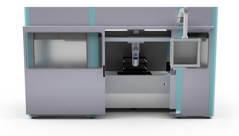
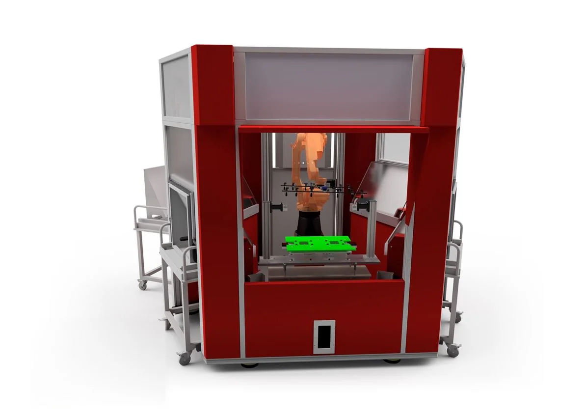
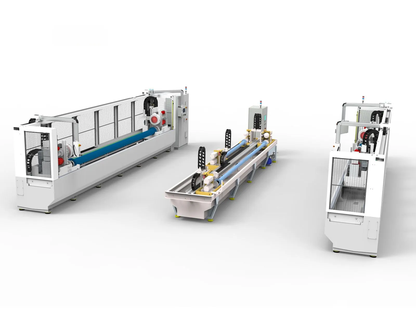
Depending on the task we combine the right building blocks: linear gantries for picking from trays, rotary indexing tables for several workstations in a small footprint and robot cells for free movement in space. We analyse the process, calculate the cycle time, design mechanics and pneumatics and create the electrical and cable planning. Our partner companies program the controller and the robot.
The automation process
Every part runs through the same sequence of steps. How fast a system works is set by the slowest step – it defines the cycle time. That is why every automation project starts with the process and only then with the machine.
How a part runs through the system
- FeedingParts arrive in order – in a tray, from a bowl feeder or on a conveyor.
- HandlingA gantry or robot picks a part and places it correctly oriented in the fixture.
- Joining & machiningPress-fitting, screwing, bonding or machining – with monitored force, stroke or torque.
- InspectionCamera, probe or force-stroke curve decide: OK or not OK.
- Sorting & placingGood parts go into the tray or onto the conveyor, rejects into the reject chute.
- Control & safetyThe PLC links all steps. Guarding, door switches and light curtains protect the operator.
Cycle time and output
Cycle time tC = index time tI + longest station time tmax
Example from the animation: tC = 0.8 s + 4.2 s = 5.0 s
Output = 3600 s/h ÷ tC = 3600 s/h ÷ 5.0 s = 720 parts/h
All stations work on different parts at the same time – so only the longest station counts, not the sum of all steps.
Building blocks of an automation system
Most systems are made of a few basic building blocks. Part, quantity and cycle time decide which of them fit.
Linear gantry
Moves in X, Y and Z over a large area – for example to pick parts from trays and place them.
Rotary indexing table
Moves the parts in a circle from station to station. Several work steps run at the same time, in a small footprint.
Robot cell
A robot moves parts freely in space – for sorting, palletising or loading machines.
Feeding technology
Bowl feeders, linear feeders, trays and conveyors bring the parts to the station in order and one at a time.
Joining & inspection
Presses, screwdrivers and cameras – monitoring force, stroke, torque or image features.
Control & safety
PLC, sensors and HMI, plus guarding, door switches and light curtains.
Scope of services
Concept & cycle time
Process analysis, sequence chart and cycle time calculation – the basis for the layout and design of the system.
Mechanics & pneumatics
Grippers, fixtures, workpiece holders, feeders and frames – with the corresponding pneumatic schematics.
Electrical & cable planning
Control cabinet, sensors and cable planning – matched to the mechanics and pneumatics of the system.
PLC & robotics with partners
Our partner companies program the controller and the robot – matched to the sequence chart and the design.
Safety & CE
Guarding and safety devices, risk assessment, operating instructions and declaration of conformity.
Installation & commissioning
Manufacturing in our network of proven partner workshops, support during installation and commissioning, acceptance and handover.
How we work
- Process analysisPart, quantity, cycle time and inspection features – the basis of the concept.
- Concept & layoutSequence chart, cycle time calculation and system layout – for decision together with you.
- DesignMechanics, pneumatics and electrical and cable planning in the 3D model.
- Controls & manufacturingProgramming with partners, manufacturing and procurement in our partner network.
- Commissioning & CEInstallation, test in cycle, acceptance, risk assessment and documentation.
Tools
Mechanics and pneumatics are created in the 3D model – schematics and parts lists match the design.
- Inventor
- AutoCAD
- Vault
- WEKA Manager CE
- PDF · DWG · STEP
What you get
- Sequence chart with cycle time calculation
- 3D model of the system with manufacturing drawings and parts lists
- Pneumatic, electrical and cable schematics
- Risk assessment, operating instructions and declaration of conformity – see Technical documentation
- Support during installation, commissioning and acceptance
Frequently asked questions
Rotary table, gantry or robot – which fits?
That depends on the process. A rotary indexing table suits many short work steps on the same part, a linear gantry picking and placing over a large area, a robot free movement in space. Many systems combine all three – like the assembly and test cell in the animation.
How is the cycle time determined?
For a rotary indexing table: cycle time = index time of the table + longest station time. With 0.8 s + 4.2 s = 5.0 s the system produces 3600 s/h ÷ 5.0 s = 720 parts per hour. We calculate the cycle time in the concept phase – stations, grippers and drives are designed accordingly.
Do you also program the controller and the robot?
Our partner companies program the PLC and the robot. We supply the sequence chart, the design and the electrical and cable schematics and support the commissioning.
Do you handle the CE marking of the system?
We create the risk assessment, operating instructions and technical documents and prepare the declaration of conformity for signature. It is signed by you as the manufacturer.
Other areas of expertise
- CAD design
- FEM & CFD simulation
- Plant planning
- Prototype development
- Technical documentation & CE
- Data management & BOMs
- Assembly instructions
- Future-oriented design
- External design department
From Pforzheim for clients throughout Germany – with on-site meetings as well as installation and assembly support. More about the region